


Induction Heating: Everything You Wanted to Know, But Were Afraid to Ask (December 2017)
November 30th, 2017
Question of the Month: What is the difference between auto-tempering and self-tempering?
Answer: Sometimes the terms auto-tempering and self-tempering are incorrectly used interchangeably. Here we will explore the differences in what these two terms really mean (Materials of this article have been adapted from the 2nd Edition of the Handbook of Induction Heating, by V.Rudnev, D.Loveless and R.Cook, CRC Press, 2017. CRC Press has granted a permission publishing these materials).
Auto-tempering. Martensitic transformation occurs over a temperature range between the Ms (martensite start) and Mf (martensite finish) temperatures. The range depends on the steel’s chemical composition and, from a practical perspective, cannot be changed by varying the quench severity. In plain carbon steels, the Ms and Mf temperature range is directly related to the carbon content. For plain carbon steels with a carbon content of 0.2% to 0.5% C range, Ms temperatures are within about a 300oC/572oF to 450oC/842oF range. Thus, freshly formed martensite will be immediately exposed to tempering temperatures and can be potentially softened. This phenomenon is commonly referred to as auto-tempering. The degree of auto-tempering becomes more noticeable with a reduction in quench severity, an increase of MS temperatures, and the mass of the heated material (for example, through heating vs. surface heating), as well as whether an interrupted quenching is used or not [1]. Alloy steels typically exhibit auto-tempering to a lesser degree compared to plain carbon steels.
Self-tempering. The principle of self-tempering (also referred to as slack-quenching) can be illustrated using the example shown in Fig. 1 [1], which shows the results of numerical computer modeling of induction surface hardening of a medium carbon steel solid shaft (50 mm/2-in. diameter) in a normalized condition using a frequency of 16 kHz. The required nominal case depth is 2.5 mm.
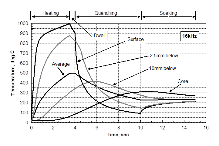 During the initial stage of induction heating, intensive heating of the surface and near-surface takes place. After 3.5 sec of heating, the surface and 2.5-mm-thick subsurface layer required to be hardened have reached suitable temperatures for austenitization, taking into consideration the non-equilibrium phase transformation caused by rapid heating. A short dwell (0.5 sec) is applied to reduce the thermal shock during the initial stage of quenching.
The temperature at the center (core) of the shaft does not increase significantly (less than 100oC) during the heating and dwell cycles. Several reasons are responsible for that, including pronounced skin effect, high power density, and short heating time, which do not permit the greater amount of heat to be conducted from the surface towards the core.
During the initial quenching stage, the high temperature of the surface layer begins to fall rapidly. After 2 sec of spray quenching, the surface temperature is drastically reduced to about 210oC/410°F. The maximum temperature reaching about 400oC/752°F will be located at approx. 10-12 mm beneath the surface. Note: The temperature at the center of the shaft continues rising during the first 6 sec of quenching.
After 6 sec of quenching, the surface temperature has decreased below 100oC/212°F, however a considerable amount of heat is retained in the interior of the shaft (the temperature at the core exceeds 300°C/572°F with the average temperature being about 225oC/437°F). If at this moment the supply of quenchant is cut off, the surface of the part will begin to be heated again due to the heat accumulated inside the workpiece.
After 5 sec of soaking (heating power and quench are not applied), the surface temperature rises to about 215oC/419°F and the core temperature will be about 260°C/500°F. Therefore, with proper selection of process conditions, this retained heat can be used to temper the workpiece.
In many cases of using plain carbon and low alloy steels for automotive applications, the self-tempering temperatures (if applied) typically do not exceed 250°C (480°F) and are usually in the 180°C (360°F) to 220°C (430°F) range.
Self-tempering provides several recognizable benefits [1]:
- It eliminates an additional operation due to incorporation of self-tempering into the hardening operation. Therefore, the capital equipment cost and total cycle time are reduced making it very attractive from a cost-reduction perspective.
- The time delay between hardening and tempering stages is virtually eliminated. Too long a time delay can be detrimental due to the potential appearance of delayed cracking.
- Since self-tempering utilizes the residual heat that is retained after hardening, there is no need to apply any additional energy for tempering making it highly energy efficient. A reduction in overall needed energy is not only associated with the reheating stage, but also with the fact that less energy is needed for the cooling stage.
- There is obviously a savings in shop floor space, because there is no need for additional space to locate tempering equipment.
All of these factors are very attractive and are the reasons for applying self-tempering in some applications. However, several precautions must be taken to ensure that the self-tempering process is performed correctly and despite the considerable benefits, self-tempering does have noticeable limitations, which restrict its broader use in industry and make furnace tempering and induction tempering more popular processes. Some of those limitations are outlined below [1]:
- Residual heat must be accurately controlled. The energy generated within the part must be monitored closely to ensure a constant amount of heat is produced. Modern induction technology allows monitoring energy levels with high precision. However, it might be more challenging to accurately control the quench severity with the same precision, in particular when hardening complex geometry components. Quench time, flow rate, temperature, concentration, and cleanliness of the quenchant also should be monitored and held within close tolerances to ensure a consistent thermal condition after quenching. It should be noted that the variations in quench severity are not only affected by actual conditions of the quenchant but they are also affected by surface condition of the workpiece, including surface roughness, presence of foreign residue from the previous operation (e.g., machining oil), and other issues. Though factors that are responsible for potential deviations in cooling intensity due to the workpiece’s surface conditions are always not desirable and should be minimized, they might not make as dramatic an impact during the first two stages of quenching (vapor blanket and nucleate boiling stages). However, they might produce a greater impact during the third stage (convective cooling), leading to measurable variations of residual heat. This will inevitably negatively affect the repeatability of self-tempering. In some cases, an infrared pyrometer may be used to monitor the self-tempering temperature of the workpiece surface.
- If applicable, self-tempering can be used in static heating, single-shot heating, and, to a lesser degree, horizontal scan hardening or continuous/progressive hardening applications. It should not be used in vertical scan hardening, because of unequal cooling conditions and variations of the accumulated residual heat in the top and bottom regions of the vertically scan-hardened workpiece.
- It is easier to use self-tempering when dealing with simple geometries (such as straight shafts, for example). Geometrical irregularities may produce localized variations in both the heating and quenching intensities (particularly when dealing with complex-geometry components) that might be sufficient to create too large a deviation in the residual heat in self-tempering.
- Some steels and cast irons have relatively low Ms temperatures and upon completion of the formation of the needed amount of martensite, there might be an insufficient amount of retained heat accumulated within the workpiece for sufficient self-tempering.
- It is more challenging to control residual heat when hardening components of small size (e.g., wires, thin-walled tubing, small diameter rods and pins). This makes it easier to apply self-tempering in cases where there is sufficient mass. However, large size workpieces with an extremely large ratio of diameter-to-thickness of the austenitized layer might also not be well suited for self-tempering. This is because the cold core may provide such an overwhelming cold-sink effect, that it eliminates the rise in temperature of the hardened surface layer needed for self-tempering.
- Self-tempering should be avoided when profiled hardening is used (for example, contour hardening of gears and gear-like components). Variations in the neighboring masses may produce a nonuniform tempering effect. The amount of heat stored, as well as the heat sink of neighboring regions, must be the same or very similar; otherwise, the temperatures obtained during self-tempering will be substantially different, resulting in unspecified temper structures.
The challenges discussed above prevent the wide use of self-tempering in industry making furnace/oven tempering and induction tempering more popular choices. At the same time, there is a group of applications where self-tempering has been successfully applied in conjunction with induction tempering combining the benefits of both processes [1]. For example, a combination of self-tempering and multi-pulse induction tempering is successfully used in a non-rotational crankshaft hardening (SHarP-C technology). In this case, the journals of a crankshaft are stationary heat treated. For most automotive crankshafts, it takes approximately 3 to 4 sec to austenitize a journal surface layer for hardening using frequencies in the range of 10 to 30 kHz (depending on the specifics of the automotive crankshaft and the required case depth). After completion of austenitization, the quenching is applied for only 4 to 5 sec, followed by 3 to 5 sec of the first soaking that accomplishes the first stage of self-tempering. Then, low-power induction tempering is applied for approximately 3 to 5 sec, followed by the second soaking and the second induction tempering. The process may be repeated to achieve desirable tempering conditions, providing a multi-pulse induction tempering effect combined with self-tempering and allowing optimization of the tempered structure. SHarP-C technology as well as the subtleties of induction tempering are thoroughly discussed in reference 1.
Dr. Valery Rudnev, FASM
Director, Science & Technology
Inductoheat Inc
www.inductoheat.com
Reference
- V. Rudnev, D. Loveless, and R. Cook, Handbook of Induction Heating, 2nd Edition, CRC Press, 2017.
Beginning in July 2016, the Professor Induction column started a new article series called “Induction Heating: Everything You Wanted to Know, But Were Afraid to Ask.” The most commonly asked questions related to different aspects of induction heating and heat treating will be reviewed and explained. All are welcome to send questions to Dr. Rudnev at rudnev@inductoheat.com. Selected questions will be answered in this column without identifying the writer unless specific permission is granted.
Recent Posts

Magnetic Flux Concentrators: An Objective Assessment
Magnetic flux concentrators (also called flux intensifiers, diverters, or controllers) …Read More »Automation of Induction Heating Systems for Billets and Other Unique Shapes
By Brian Lockitski, Inductoheat; Carl Wesolowski, Inductoheat; Michael Zaharof, Inductoheat; …Read More »Induction Heat Treatment Challenges in a Highly Digitized World
The technology of heat treating by means of electromagnetic induction is advancing at …Read More »Induction Heating: Everything You Wanted to Know, But Were Afraid to Ask (February 2018)
Question of the Month: We are planning to use induction …Read More »Induction Heating: Everything You Wanted to Know, But Were Afraid to Ask (March 2017)
Question of the Month: We use an induction process where …Read More »